Why your circuit diagram is a map of logic, not a physical blueprint
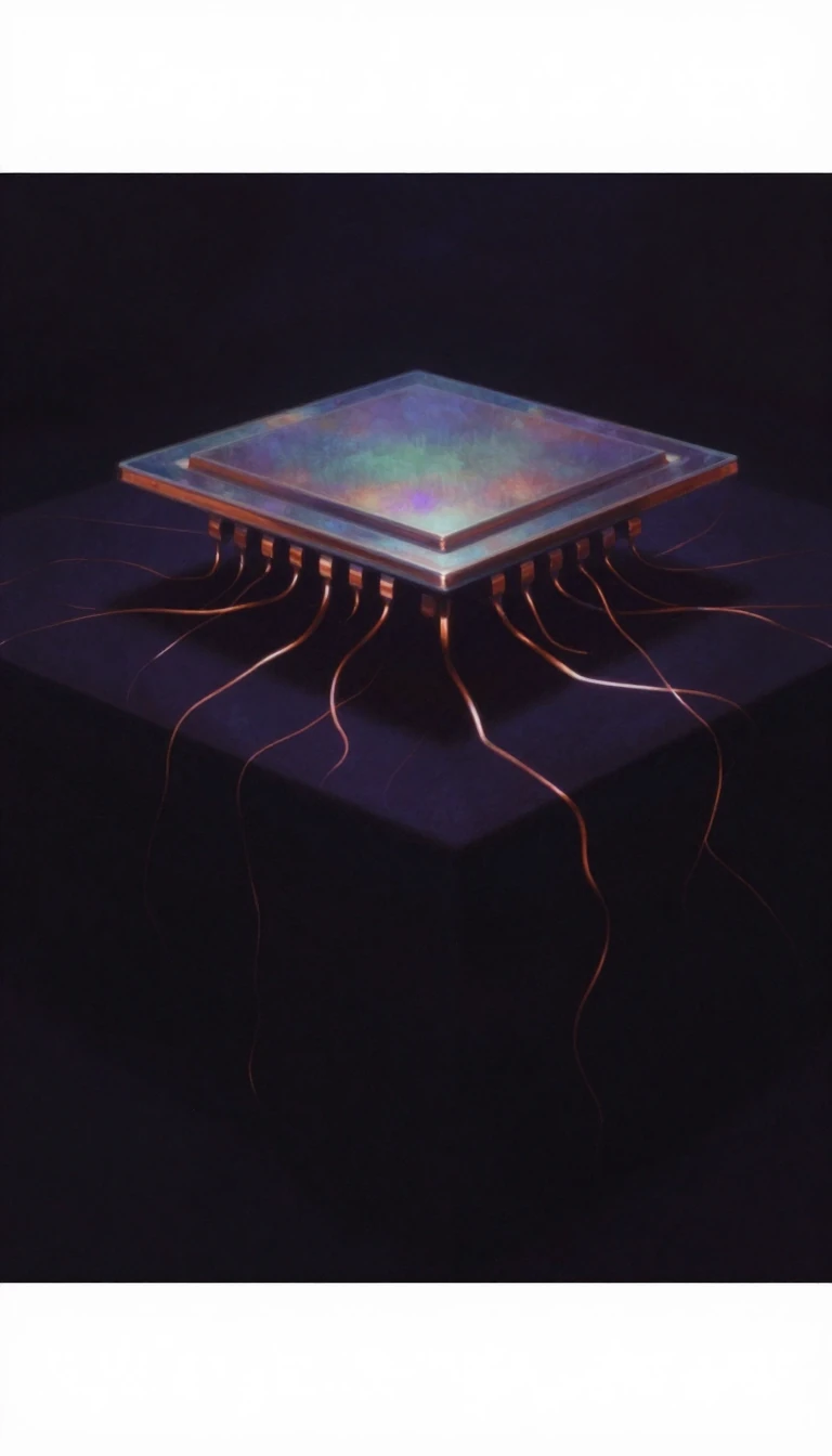
In short: A circuit diagram is not a picture of how a device is built; it is a symbolic map of how electricity flows. While it shows every connection, it ignores physical placement entirely. Understanding these standardized symbols and signal paths is the essential bridge between abstract design and functional hardware.
At its core, a schematic diagram is a graphical representation of an electrical circuit that prioritizes logical connectivity over physical reality. Unlike a layout or wiring diagram, which depicts where components actually sit inside a device, a schematic uses standardized symbols to illustrate how electricity moves from point to point. This abstraction allows engineers to design, construct, and maintain complex electronic equipment without being constrained by the physical dimensions of the hardware itself.
The evolution of these diagrams reflects the history of engineering. Many symbols, such as the zig-zag line for a resistor, originated from the physical construction of early components—in this case, wire wrapped to avoid inductance. Today, international standards like IEC 61346 and IEC 61082-1 govern these representations, favoring simplified shapes like oblongs for resistors. Even the way we draw connections has matured; to avoid the ambiguity of dots that might vanish in a photocopy, modern practice favors T-junctions or clear semi-circle 'jumps' for insulated wires.
The design process follows a rigorous flow, beginning with a schematic that is captured into a netlist. This initial state, often called a 'rat's nest' due to its chaotic web of criss-crossing lines, is then refined by electronics design automation (EDA) tools. These tools route the tracks to create the final artwork for a printed circuit board (PCB). Whether organized left-to-right to show signal flow or in a ladder logic format for relays, these diagrams remain the universal language of electronics, helping students and professionals alike visualize the invisible paths of power.
Opens the Intellect+ feed with this card first. Swipe up for the next one.
Sources
- Summary by Intellect · source: Circuit diagram
To cite this card, link to https://intellectplus.co.uk/app/technology-circuit-diagram.
How we source, check and correct cards: Editorial standards.
General information, not professional advice. Spotted an error? Flag the card or see corrections and complaints.
Intellect Plus is a visual educational discovery platform for exploring fascinating facts and ideas. Brain Food, Not Brain Rot. What is Intellect Plus?
Related
More in Electronics · More in Technology · Latest · A–Z · All topics
